Home / FAQ / TECHNICAL ARTICLES / OVERVIEW OF POWER SUPPLY I/O AND COMMUNICATION INTERFACES

Overview of Power Supply I/O and Communication Interfaces
With the increasing intelligence and diversification of electronic devices, power supplies are no longer merely devices that provide stable power. Their I/O interfaces and communication functions have become increasingly significant. Whether in servers, industrial automation, or data centers, modern power supplies now play a crucial role in system integration and monitoring. This technical article will provide an in-depth exploration of the I/O and communication features of power supplies, including basic interface designs, extended functionalities, and the application of communication protocols.
1. Power Supply I/O Interfaces and Extended Features
The I/O interfaces of power supplies provide essential control, signaling, and communication functions for systems. The AC input interface is responsible for receiving alternating current (AC) or direct current (DC) power. After rectification and conversion, the output interface delivers stable DC power to meet the requirements of various devices.
I/O connections can be customized based on customer needs, offering a range of options, including IEC-standard sockets, screw terminals, and branded connectors such as JST, JWT, WST, or TKP. Tiger Power can also design proprietary connectors or cables to flexibly adapt to diverse operational environments.
In addition to basic input and output power conversion, power supplies can offer multiple extended features:
(1) Power Good Signal:
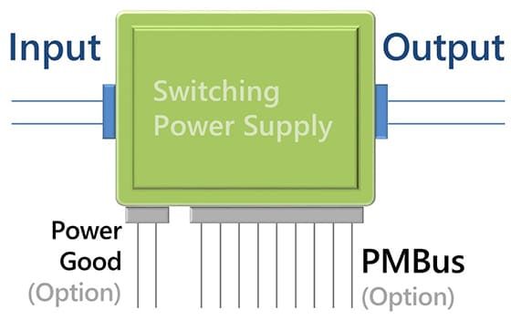
This unidirectional signal communicates the operational status of the power supply to the motherboard. It helps the system monitor whether the power supply is running stably, enhancing the reliability of connected devices.
(2) Standard PMBus Bi-Directional Communication:
This protocol enables interaction between the power supply and the host system, allowing the motherboard to acquire real-time operational data such as voltage, current, and temperature. It also provides alerts and control functions, achieving precise power management and monitoring. This feature is particularly well-suited for servers, data centers, and industrial automation equipment.
(3) Connection Port Options:
Tiger Power can develop customized solutions based on customer requirements, including gold fingers, various pin connectors, or proprietary terminals and cables to flexibly accommodate different application needs.

Illustration of Power Supply Interfaces
2. What is the Power Good Signal (PG Signal)?
The Power Good Signal, also known as Power Good (PG Signal) or Power OK Signal (PW OK Signal), is a unidirectional status signal. It is primarily used by power supplies to notify the motherboard that the power supply is ready, ensuring all output voltages are within normal ranges and guaranteeing stable system startup and operation.
(1) Introduction to the Power Good Signal Terminal
The Power Good Signal terminal is a critical interface in power supplies designed to output the PG Signal (or PW OK Signal). Its design varies to meet the needs of different applications:
A. Standalone Terminal Output:
Besides the basic I/O terminals, the Power Good Signal can be designed as a standalone output for straightforward and clear connections to the motherboard.
B. Gold Finger or Ribbon Cable Output:
In server power supplies (e.g., CRPS) and industrial automation applications, the PG Signal is often output through gold fingers or ribbon cables. A dedicated pin, commonly labeled as DC_GOOD or PWOK, ensures compatibility and recognizability with motherboards or other systems.
(2) Operating Principles of the PG Signal
The PG Signal operates as follows: once all output voltages stabilize and meet predefined standards, the signal switches from low to high voltage.
A. High Voltage:
Indicates stable power output and readiness.
B. Low Voltage:
Suggests potential abnormalities, such as power outages, aging components, or unstable input voltage.
C. Recovery:
When the abnormal condition is resolved, the power supply restores stable output, regenerates the PG Signal, and sends it to the motherboard to signal readiness for system reboot. The motherboard monitors the PG Signal’s state (high/low voltage) to determine power supply status, ensuring system stability.
(3) Customization of the PG Signal
Tiger Power can customize the PG Signal voltage thresholds, logic settings, or operating modes under specific conditions based on customer requirements, such as:
A. Low voltage indicating normal operation.
B. High voltage indicating abnormal system status.
C. Flexible configurations to meet diverse application needs.
(4) Vsb (Standby Power)
Some power supplies provide multiple output voltages, including a Vsb (standby power) voltage, widely used in computers, servers, and mid-to-high-end equipment:
A. When connected to the mains, Vsb continuously supplies minimal current to the motherboard.
B. Regardless of whether the equipment is powered on, this voltage provides the initial power required for motherboard startup and basic operation.
(5) Coordination Between PG Signal and Vsb
In practical applications, the PG Signal and Vsb often work in tandem. The power supply uses an independent circuit to provide Vsb to the motherboard for initial power, while confirming stable output voltages before sending the PG Signal.
A. If the equipment cannot operate normally, the motherboard signals the power supply to halt other power outputs, protecting equipment from power-related damage.
B. Once the motherboard signals readiness, the power supply resumes output, ensuring operational reliability.
(6) Power Good Signal and Alarm Delay Timing
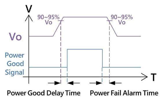
A. Output Voltage (Vo):
Power output is considered stable when the voltage reaches 90%–95% of the rated value.
B. Power Good Signal (PG Signal):
When Vo is within the stable range (≥90%–95%), the PG Signal indicates “normal.” If Vo falls below this range, it indicates “abnormal.”
C. PG Signal Delay Time:
After Vo stabilizes (approximately 90%–95% of the rated value), the system waits 0.1–0.5 seconds before activating the PG Signal to prevent false alarms due to transient fluctuations. This +5V signal indicates stable power output and successful internal self-checks.
D. Power Fail Alarm Time:
The power diagnostic function continuously monitors output voltage and stability. In cases of instability or failure due to power outages, aging components, or abnormal input power, the system cancels the PG Signal at least 1 millisecond in advance, notifying the motherboard to take protective measures and prevent equipment damage.

Power Good Signal Timing Diagram
3. What is PMBus (Power Management Bus)?
The Power Management Bus (PMBus®) is an open-standard digital power management protocol that enables data communication through digital signals. It transmits key parameters such as voltage, current, temperature, and power to ensure efficient coordination of all power-related components.
(1) Features and Advantages of PMBus®:
A. Designed for Power Applications:
Provides a standardized command set for monitoring and controlling power states, including input/output voltage, current, power, and temperature.
B. Bidirectional Communication:
Supports interaction between the host and power supply, allowing real-time monitoring and parameter adjustments.
C. Plug-and-Play Compatibility:
A unified command structure simplifies integration across brands and platforms.
D. Dynamic Adjustment Capability:
Enables dynamic parameter adjustments, such as output voltage settings or current limits.
(2) Operating Mechanism:
Utilizes SMBus (I²C) as the underlying hardware protocol, with transmission rates up to 100kHz or 400kHz.
Supports multiple devices sharing the same bus, making it suitable for systems integrating multiple-output power supplies or multiple power modules.
(3) Applications:
A. Advanced server power management.
B. Power systems in data centers requiring precise power regulation.
C. Power monitoring for industrial automation equipment.

The PMBus name and logo are trademarks of SMIF, Inc.
4. PMBus® Data Exchange and Functional Overview
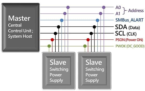
The Power Management Bus (PMBus®) standard uses two lines, SCL and SDA, to enable bidirectional data exchange, facilitating communication between the power supply and the motherboard system.
SCL (Serial Clock Line): The clock signal line responsible for synchronizing signals between the power supply and the motherboard system.
SDA (Serial Data Line): The data transmission line responsible for bidirectional data transfer, ensuring accurate data transmission and reception based on the timing of SCL.
These two lines work in tandem, with SCL controlling the timing to ensure accurate data transmission on SDA. This transmission method enables the PMBus protocol to achieve efficient bidirectional communication and coordination between the power supply and the motherboard system.
Below are the main functions of PMBus:
(1) Monitoring Power Status:
A. Voltage and Current:
The motherboard system can monitor the input and output voltage and current of the power supply to ensure stable operation, including verifying the stability of the power outlet or the device’s power consumption.
B. Internal Temperature:
The motherboard system can monitor the internal temperature of the power supply to prevent overheating. If the temperature exceeds safe limits, PMBus issues a warning or activates protection mechanisms.
C. Fan Speed:
The motherboard system can monitor the speed of cooling fans to ensure proper heat dissipation. If fan speed is abnormal or a fault occurs, the motherboard system issues an alert.
(2) Diagnostics and Alerts:
A. Error Indications:
The power supply can send error or warning messages to the motherboard system via PMBus in cases of overload, overvoltage, undervoltage, overcurrent, fan failure, or excessive temperature.
B. Real-Time Alerts:
The power supply uses the SMBus_ALERT or SMBAlert pin to send alert signals to the motherboard system, prompting appropriate countermeasures.
(3) Control Functions:
A. Power Switch:
Allows the motherboard system to remotely control the power supply’s on/off state through PSON or in combination with the PSKILL pin, eliminating the need for manual operation.
B. Fan Speed Adjustment:
Automatically adjusts fan speed based on the motherboard system’s requirements to enhance cooling efficiency or reduce noise.
(4) Logging and Tracking:
A. Historical Data:
Records operational parameters (e.g., power consumption, temperature) to aid in performance analysis and troubleshooting.
B. Serial Number and Model Information:
Provides basic device information for easier maintenance and management.
(5) Multi-Power Supply Management:
A. A0 / A1 Addressing:
Uses A0 and A1 address pins to distinguish between different power supplies, ensuring accurate identification and management by the motherboard system.
B. Load Synchronization Coordination:
When multiple power supplies are used in a system, PMBus coordinates load distribution among them to ensure stable and efficient power delivery.

Illustration of communication wiring between the motherboard system and the power supply (1)
5. Introduction to Other Power Management Functions
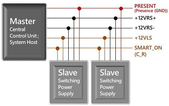
(1) Present (or Presence, GND) Signal
This signal is typically used in multi-power systems to help the motherboard system identify which power modules are currently installed. It notifies the motherboard system whether a power supply is physically connected to ensure operational safety and reliability. When a power supply is inserted into the motherboard system, the PRESENT signal sends a notification to the host, indicating that “this power supply is installed.” If the power supply is removed, the host will no longer receive the signal, thereby recognizing that the device has been disconnected.
(2) +12VRS+ and +12VRS- Signals
This pair of Remote Sense signals monitors the main output voltage (+12V) to compensate for voltage drops caused by wire resistance (IR Drop). Using these signals, the power supply can dynamically adjust its output to ensure that the load side remains stable at +12V, further ensuring the stable operation of the equipment.
A. IR Drop Compensation:
The power supply measures the actual voltage at the load side based on the +12VRS+ and +12VRS- signals and dynamically adjusts the output voltage to compensate for the drop, with a maximum compensation of 500mV.
B. Signal Measurement:
+12VRS+: Measures the positive voltage (+12V) at the load side.
+12VRS-: Measures the ground voltage (GND) at the load side.
(3) +12VLS Signal
This signal is primarily used to balance the load distribution among multiple power supplies, preventing any single power supply from being overloaded. The +12VLS signal is widely applied in systems requiring collaboration among multiple power supplies, such as servers and data centers. The host system can roughly assess the system load by reading the voltage value of this signal. It not only coordinates load distribution among multiple power supplies but also provides a reference for monitoring power status, thereby enhancing system stability and operational efficiency.
A. Load Balancing:
When two or more power supplies operate in parallel, the +12VLS signal helps them share the load proportionally and fairly.
B. Signal Characteristics:
+12VLS is an analog output signal that outputs a voltage corresponding to the power supply’s load proportion. The relationship between the load proportion and the +12VLS signal is as follows:
25% Load: +12VLS outputs approximately 2V.
50% Load: +12VLS outputs approximately 4V.
100% Load: +12VLS outputs approximately 8V.
(4) Smart_on (or C_R) Signal
The Smart_on (or C_R) signal can be used in conjunction with the +12VLS signal to switch redundant power supplies to a low-power cold standby state when the system load is low. This function ensures that only the necessary power supplies are activated to support system operation, while the others enter standby mode. This effectively reduces energy consumption and extends the lifespan of the power supplies, making it particularly suitable for environments like servers and data centers that require multi-power collaboration.


